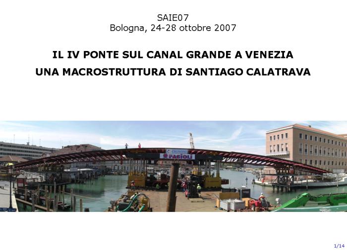
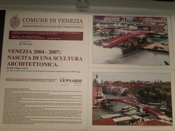
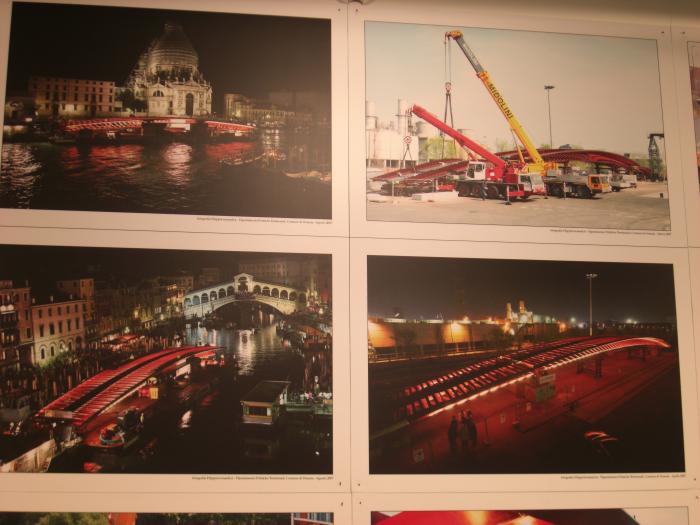
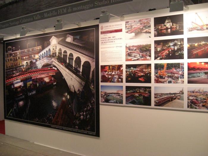
THE NEW FOOTBRIDGE IN VENICE
"IV PONTE SUL CANAL GRANDE"
CONCEPT AND DESIGN
ARCH. ING. SANTIAGO CALATRAVA VALLS
GENERAL CONTRACTOR
IMPRESA CIGNONI SRL
FOOTBRIDGE ERECTION AND COMPLETION SUPERVISION
STUDIO ING. GIORGIO ROMARO
-----------------------------------------------------
Extract from the technical presentation held at SAIE 2007 Exhibition
by Ing. Giorgio Romaro, Arch. Chiara Romaro and Ing. Loris Ziero
Courtesy of Studio Ing. Giorgio Romaro
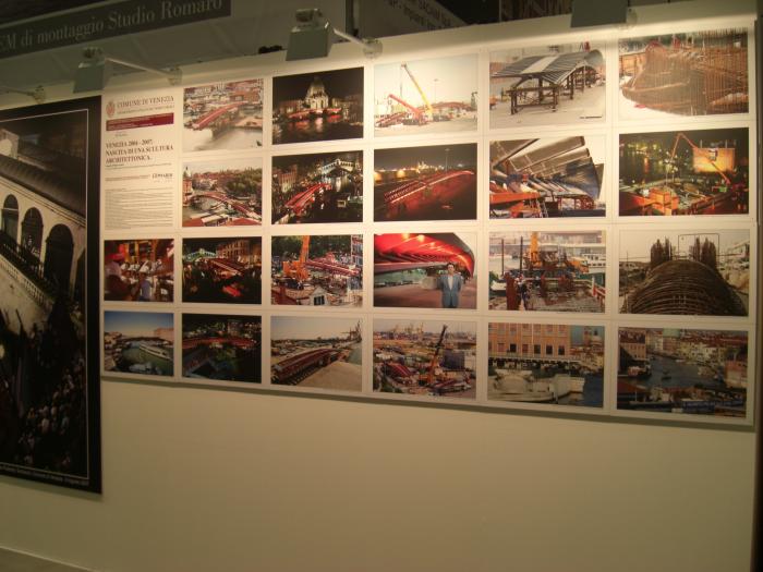
Slides from the presentation held by Ing. Giorgio Romaro - Studio Romaro
-----------------------------------------------------------------------------------------------
Comune di Venezia - Assessorato ai Lavori Pubblici di Venezia
Dipartimento Politiche Territoriali
Concept and design : Arch. Ing. Santiago Calatrava - Zurigo
General Contractor : Impresa Cignoni srl
On site steelwork subcontractors : Lorenzon Techmec System S.p.A, Siro Marin,
Officina Metalmeccanica di Inzitari Obenito, Omar Costruzioni, La Fratta
Saldature
Design of foundations : Prof. Renato Vitaliani, Prof. Francesco Colleselli
Erection sequence : Studio Bolina - Mestre, Prof. Roberto Di Marco
Erection and steelwork detailing supervisor : Studio Giorgio Romaro
Static test : Prof. Enzo Siviero
Transportation and heavy lifting : Fagioli Spa
Provisional cables for temporary erection : Tensacciai Spa
Monitoring and abutment displacement control devices : 4 EMME SERVICE Spa
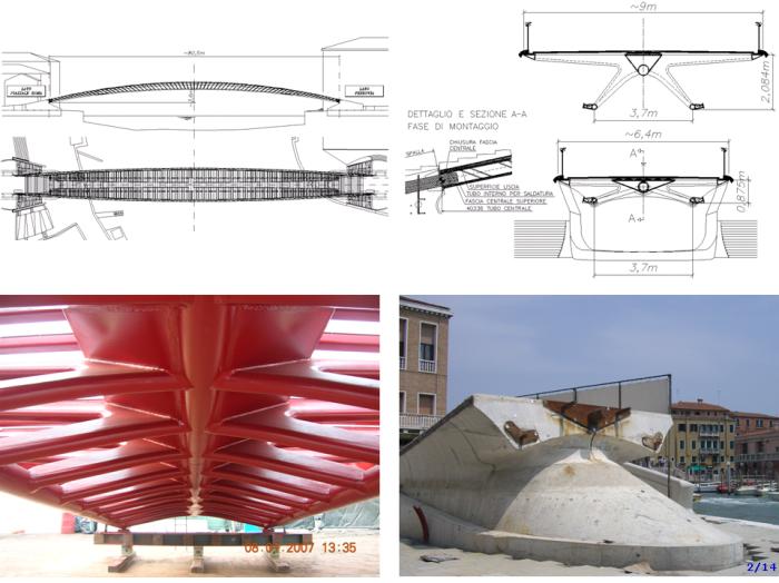
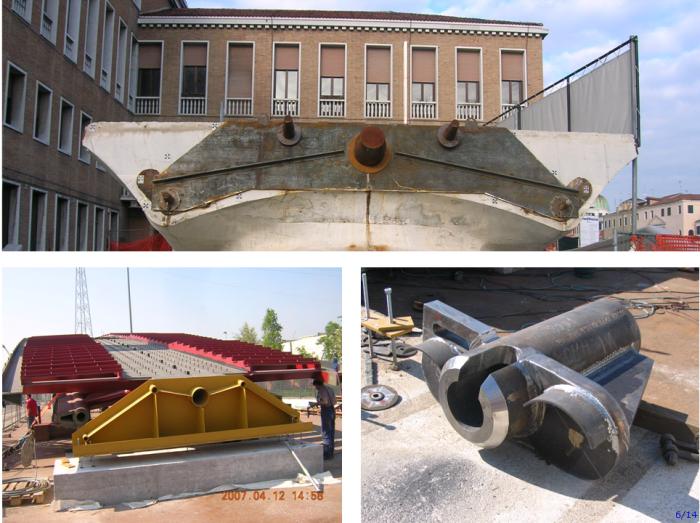
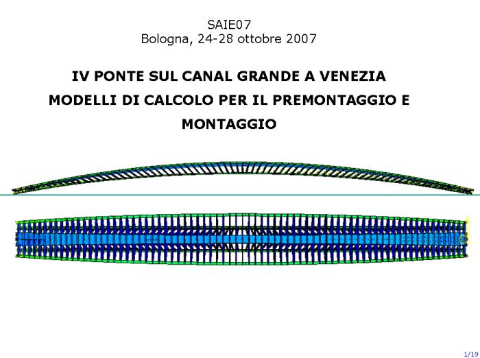
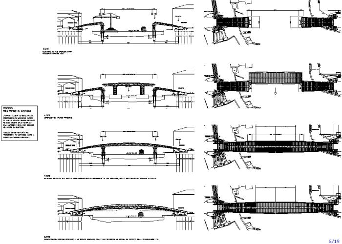
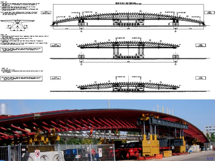
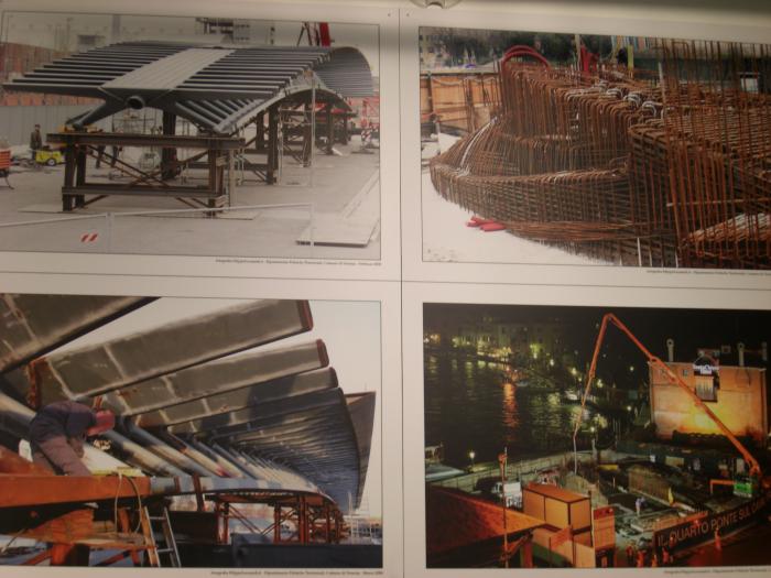
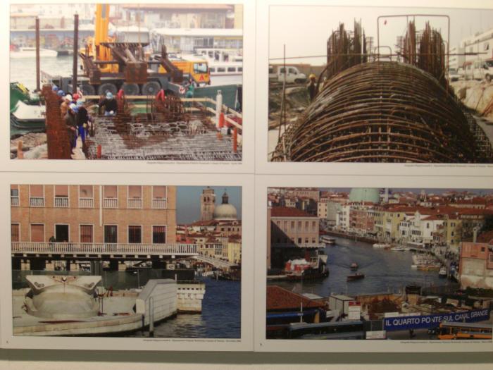
Clockwise: footbridge plan and side view; abutment and mid span cross sections with a detail of the abutment plug;
abutment (railway side) with 5 steel plugs; the lateral segment temporarily supported on the quay
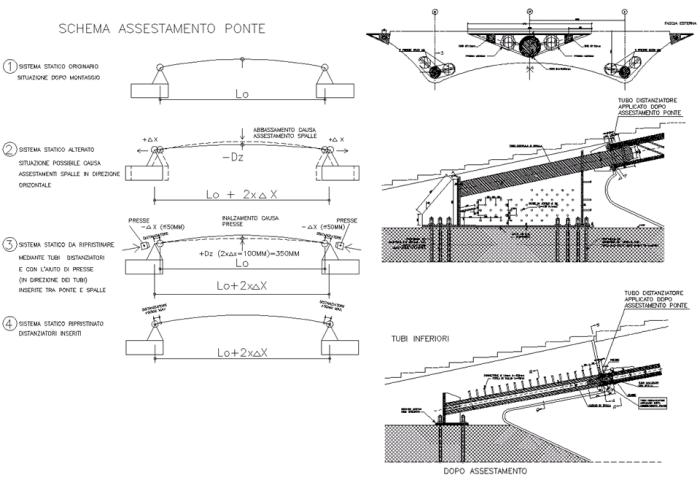
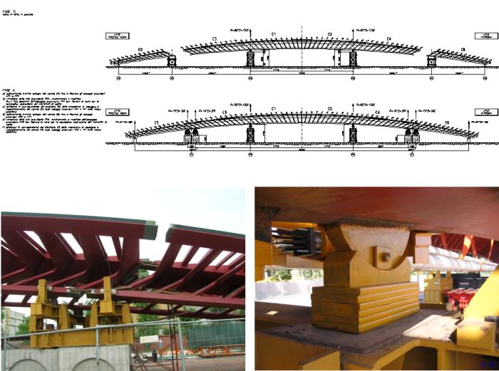
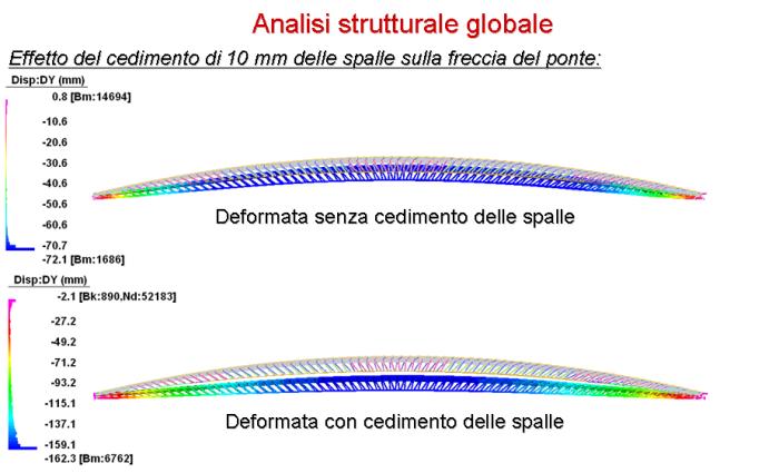
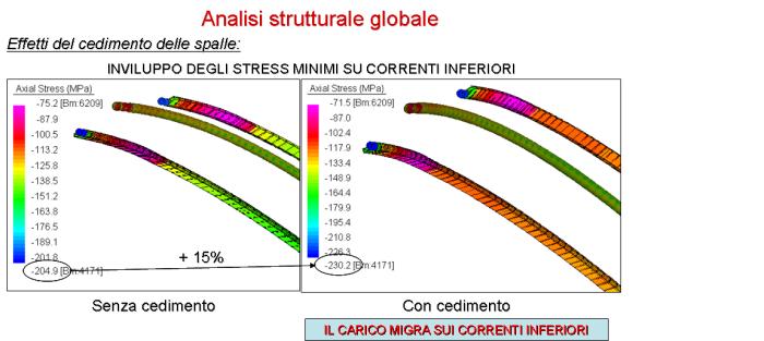
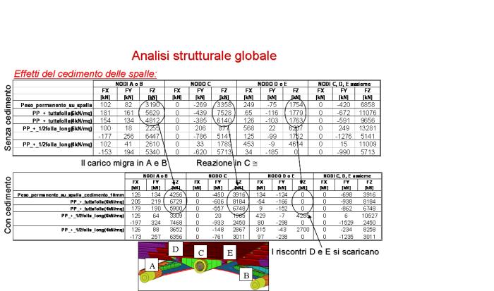
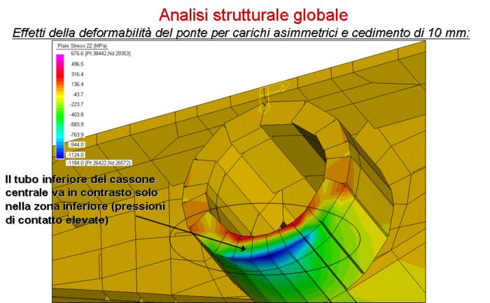
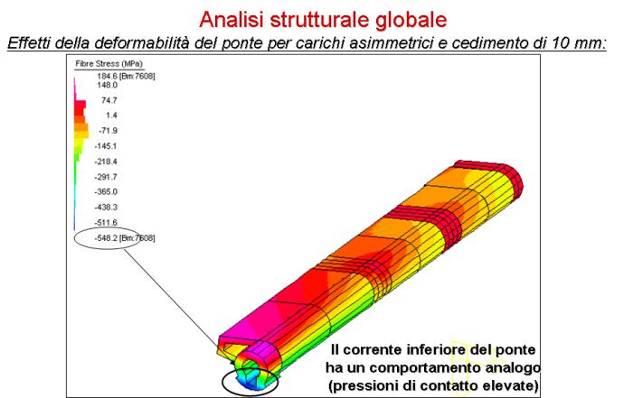
Extract from Calatrava design report (left) and drawings (right): recovery from possible side settlements.
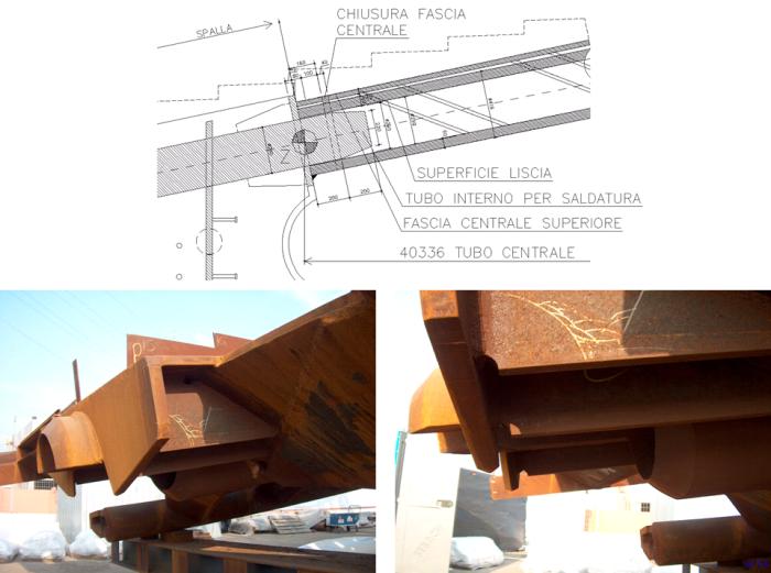
Difference between the as-built geometry and design drawings at the bridge-abutment interface.
Slip joint redesign due to on site tolerances.
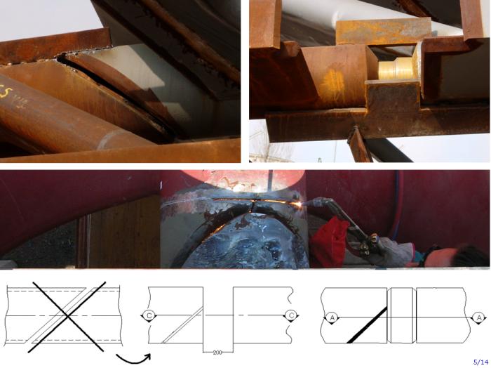
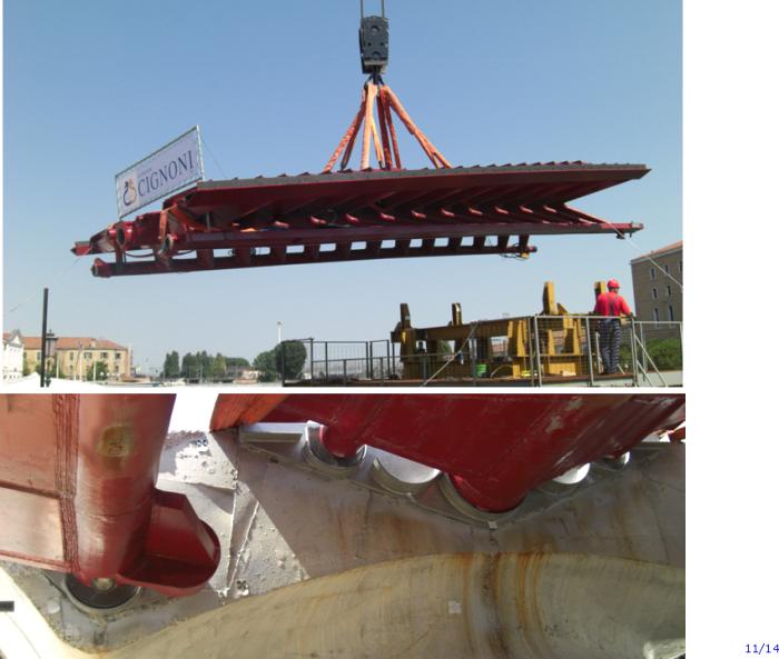
Auxiliary steel plate used to recover the location of steel plugs (top); steel plug device used for preliminary erection;
further element design during the preliminary erection and needed to provide better support and load transfer at the lower arches.
Provisional cable tendons: fixed and floating end detail.
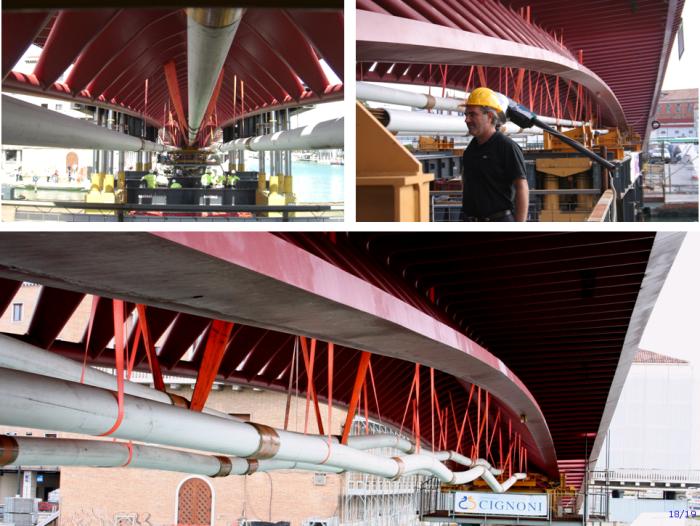
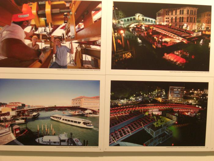
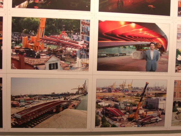
Lifting of the central footbridge segment during preliminary erection:
detail of auxiliary support elements connected to the main structure.
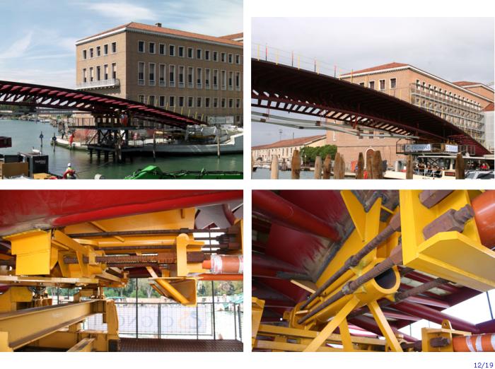
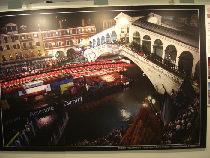
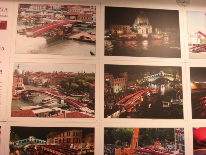
Erection of lateral segment (“Piazzale Roma” side) on “Canal Grande” and bridge abutment interface detail.
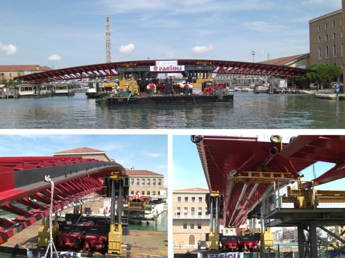
Erection of central segment on “Canal Grande”.
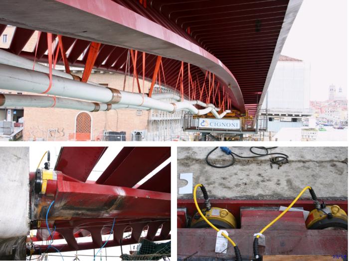
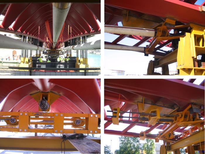
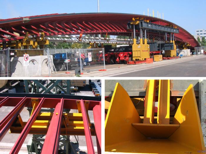
De-tensioning of provisional cable tendons and jacks installed on abutments for horizontal force control.
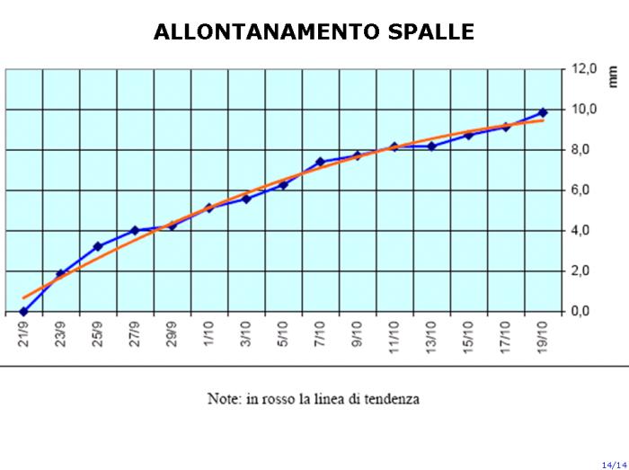
Extract from 4EMME SERVICE technical report, with abutment horizontal settlement
during the first month after the removal of temporary supports.
Slides from the presentation held by Arch. Chiara Romaro - Studio Romaro
-------------------------------------------------------------------------------------------------
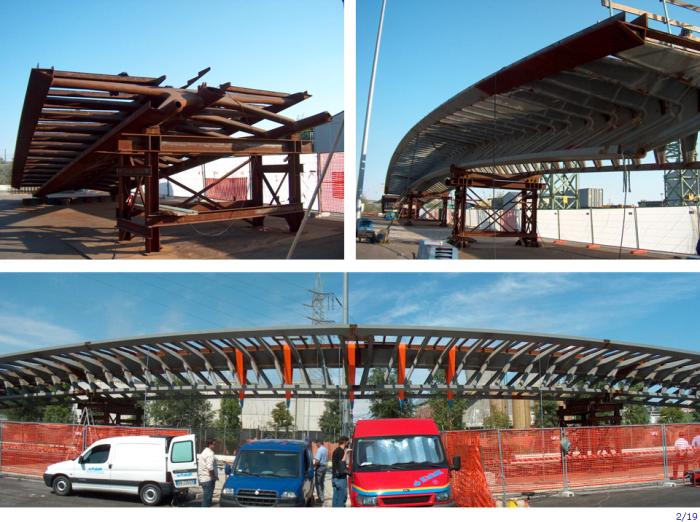
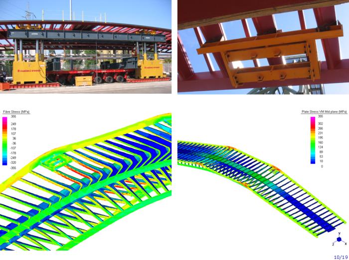
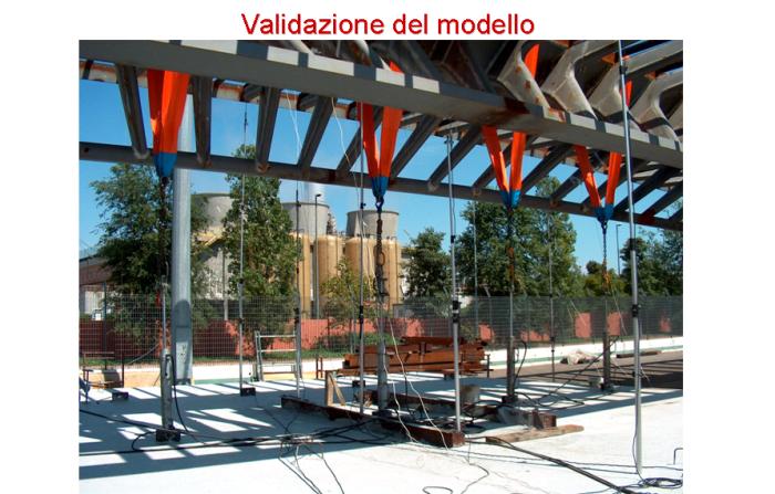
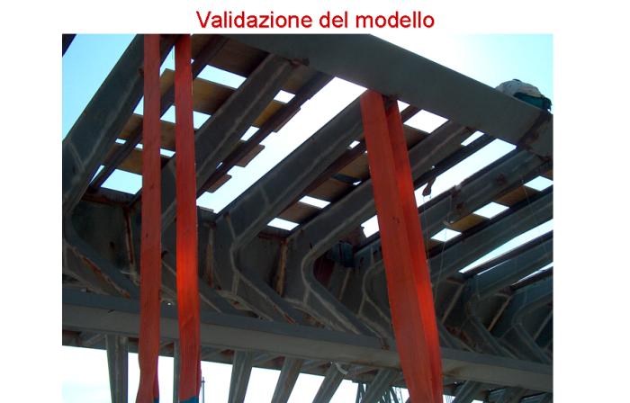
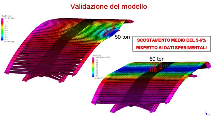
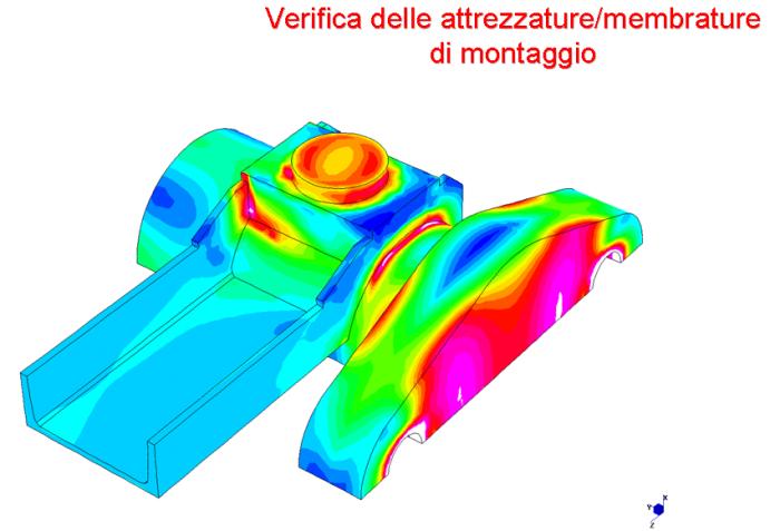
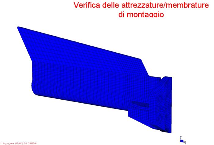
Central and lateral footbridge segments during load tests performed on the quay.
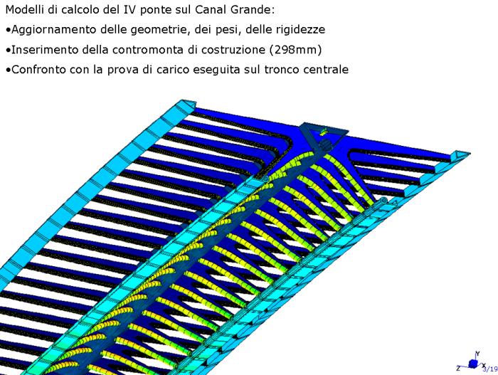
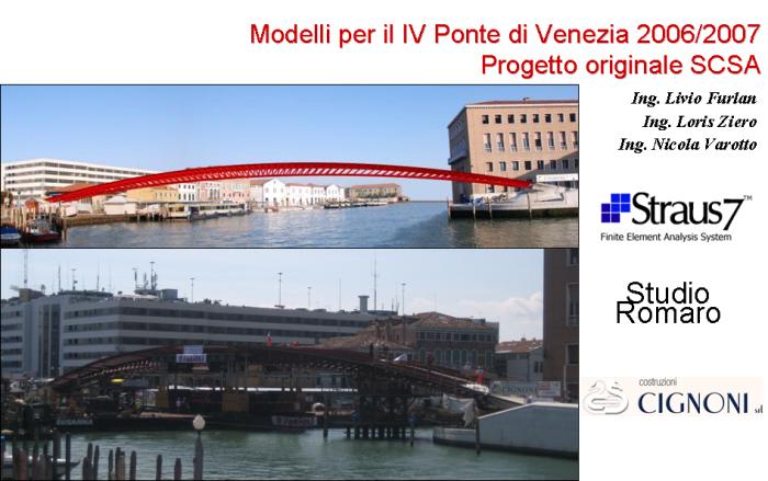
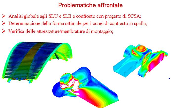
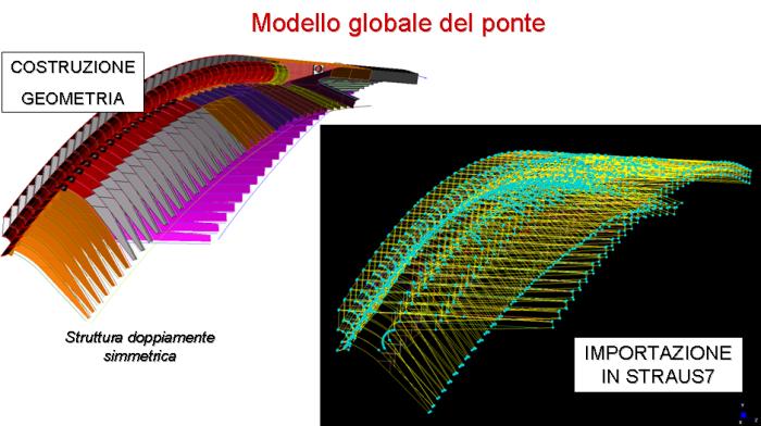
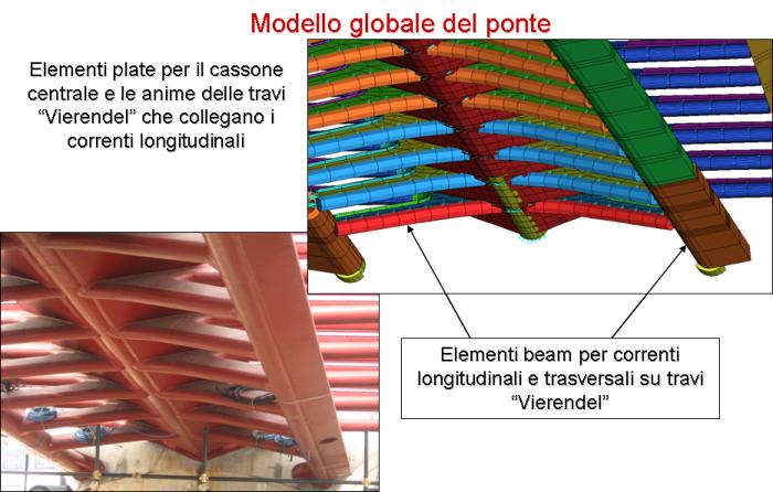
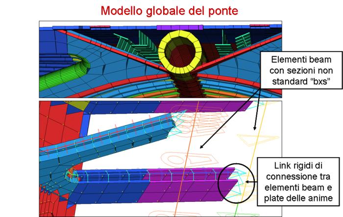
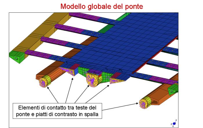
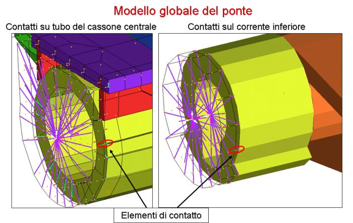
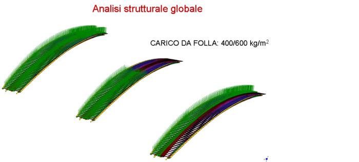
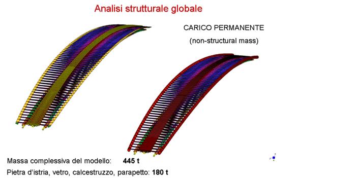
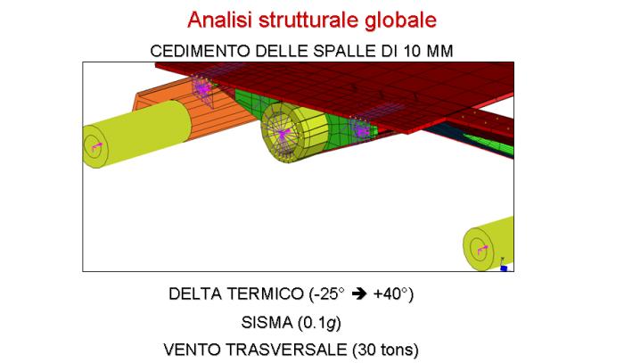
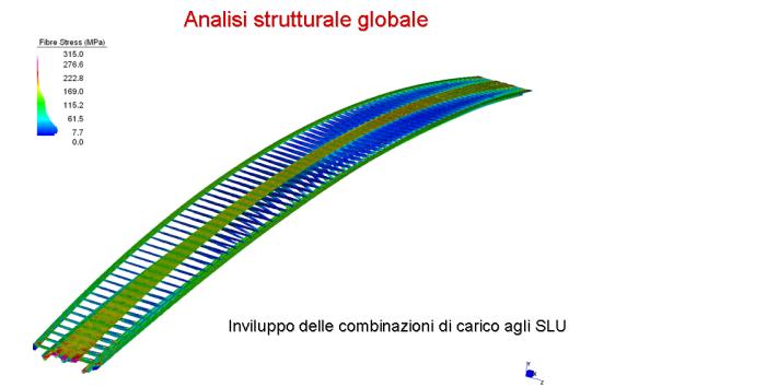
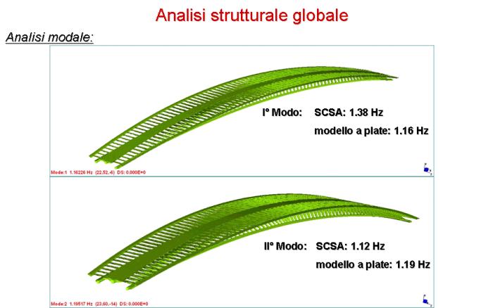
View of the global finite element model for the “IV Ponte su Canal Grande” footbridge.
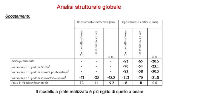
Bridge cross section and finite element mesh for a beam and beam/plate model.
Extract from Santiago Calatrava LLC erection drawings.
Preliminary erection drawings and temporary falsework support details.
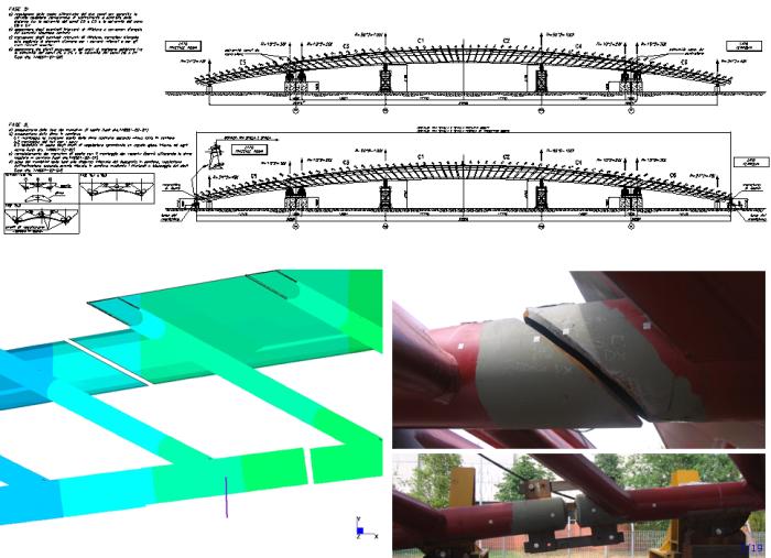
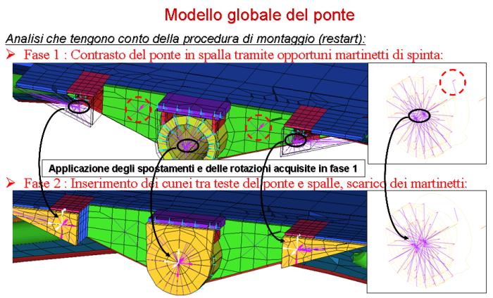
Preliminary erection drawings and finite element models
to investigate the relative displacements at the interface; view of the real joint.
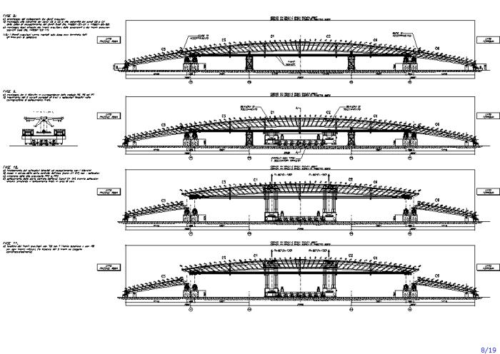
Preliminary erection procedure and testing of temporary devices: assembling of provisional tendons;
installation of side support devices and insertion of the “Self Propelled Modular Transporters” (SPMT);
Hydraulic jack lifting and release from temporary falsework; partial tensioning of provisional cables.
Preliminary erection procedure and testing of temporary devices: simply supported restraint conditions
for the central segment; final tensioning of provisional tendons to enforce compatibility
at the interface between segments; further lifting to release the support structures
located at the top of the temporary falsework to allow their final placement on site;
de-tensioning of provisional cables; lowering on SPMTs and preparation for transportation.
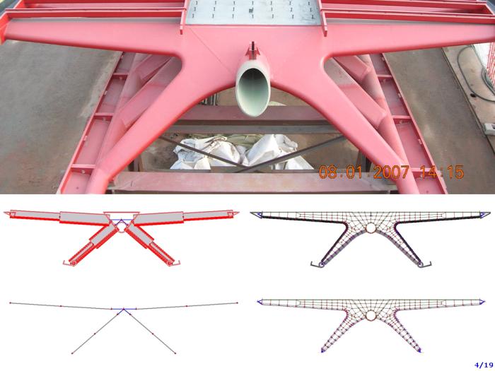
Picture and detail of the anchor system on each side of the footbridge;
footbridge finite element model in the lifting configuration.

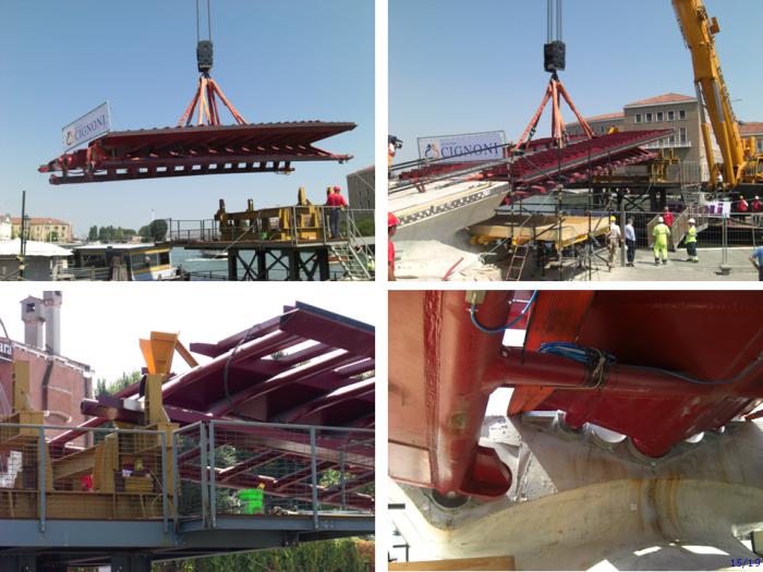
Three provisional tendons and tensioning devices.
View of provisional tendons after erection in Venice: global view and detail of tensioning devices.
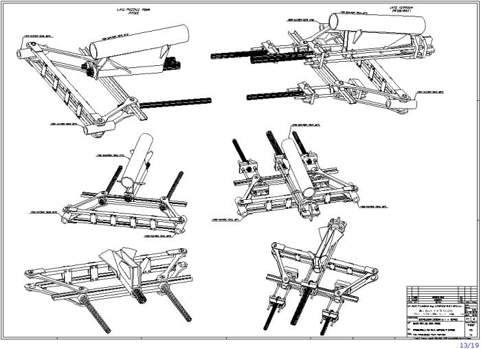
3D drawing for the fixed (left) and floating (right) anchor devices for provisional tendons.
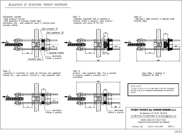
Tensioning sequence for provisional tendons.
Erection of lateral segment (“Piazzale Roma” side) on “Canal Grande”.
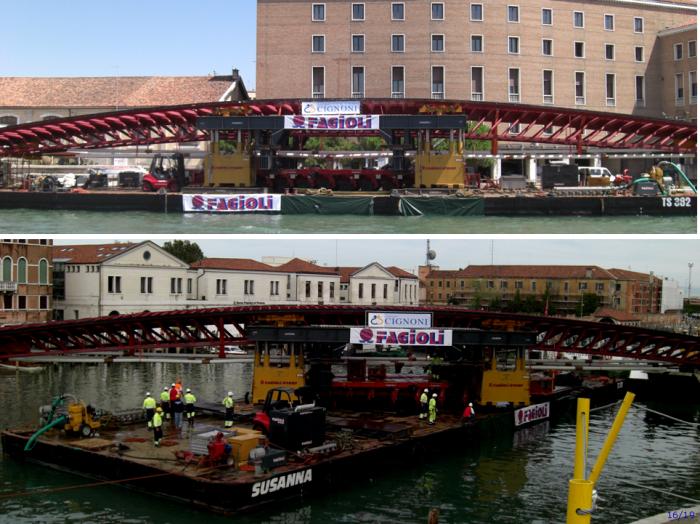
The central segment on the barge; rotation maneuver of the central segment.
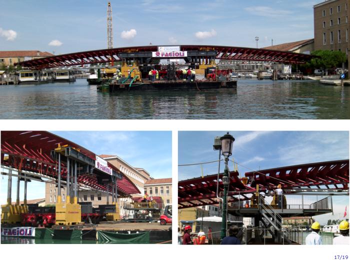
Approaching, lifting and final release of the central segment.
View of provisional cables while tensioned; release of temporary supports;
de-tensioning of provisional cables after installation of final welds: all the weight is carried by the left and right abutments.
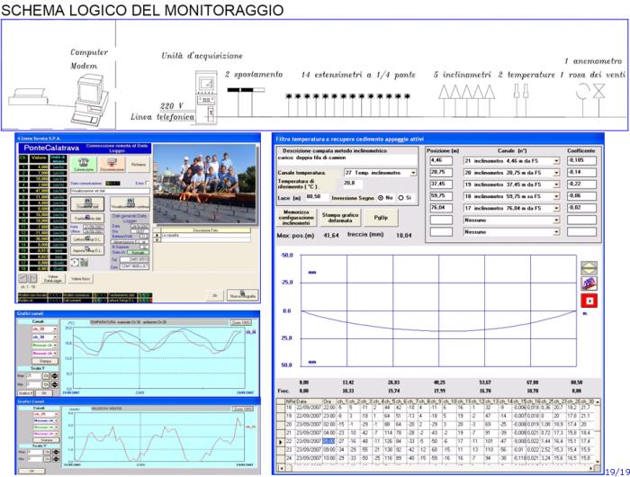
Extract from 4EMME SERVICE technical report with the continuous monitoring system during erection.
Slides from the presentation held by Ing. Loris Ziero
--------------------------------------------------------------------


For more information please contact us by e-mail:
straus7@hsh.info
-------------------------------------------------------------------------------------------------
--------------------------------------------------------------------