JERUSALEM LIGHT RAIL TRANSPORTATION
Jerusalem Municipality and Israeli Ministry of Transport
Conception ARCH. SANTIAGO CALATRAVA VALLS
Supply of the steel structure
and design/supervision of the erection CIMOLAI SpA

All text and images are provided courtesy of CIMOLAI SpA - Pordenone - Italy
General Concessionaire: CityPass Consortium (Connex Transport AB-Vivendi Group,
Alstom Train Manufacturer, Ashtrom Construction and Infrastructures, Pollar Investments)
General Contractor for Civil Works: Moria LTD
Concrete Contractor: Ramet LTD
Steel Contractor: Koor Metals LTD
Project: Steel works of Jerusalem LRT Bridge
- design review + shop drawings;
- supply: pylon, deck (partial) and parapet;
- design of the erection and supervision on site.
Sub-Contractor: Cimolai SpA
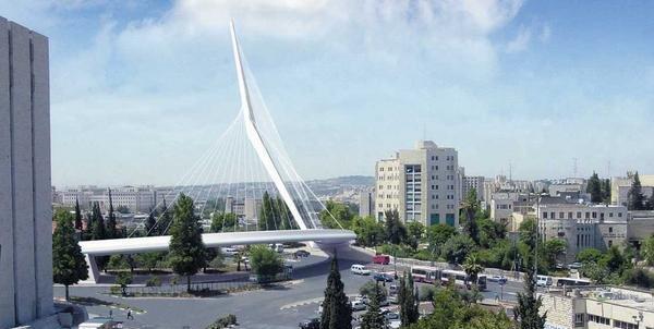
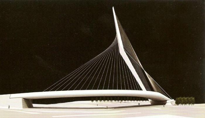
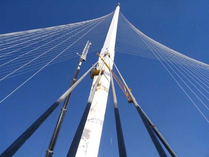
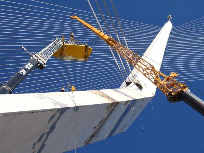
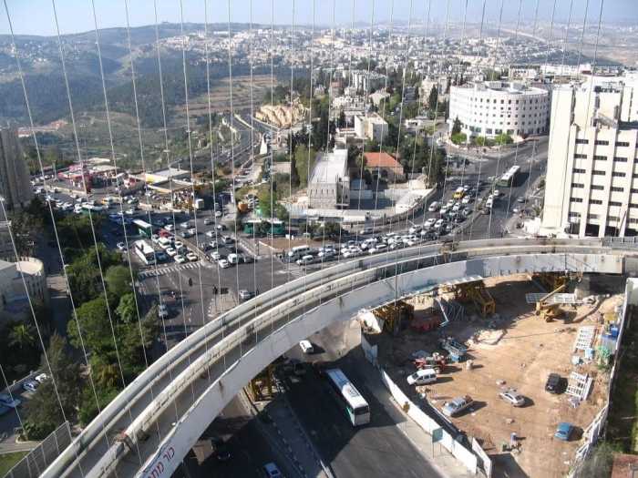
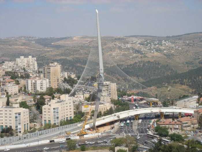
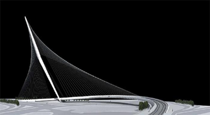
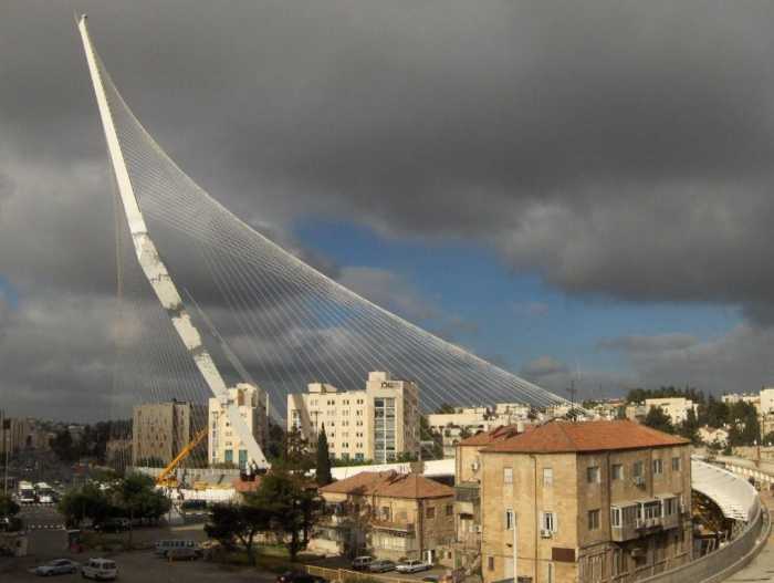
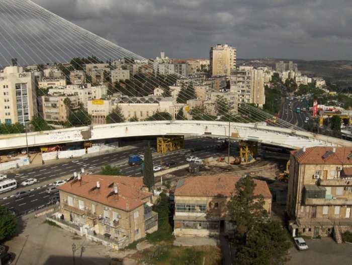
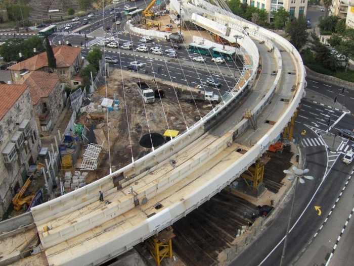
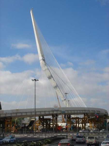
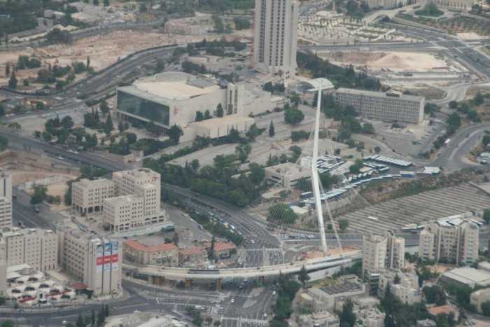
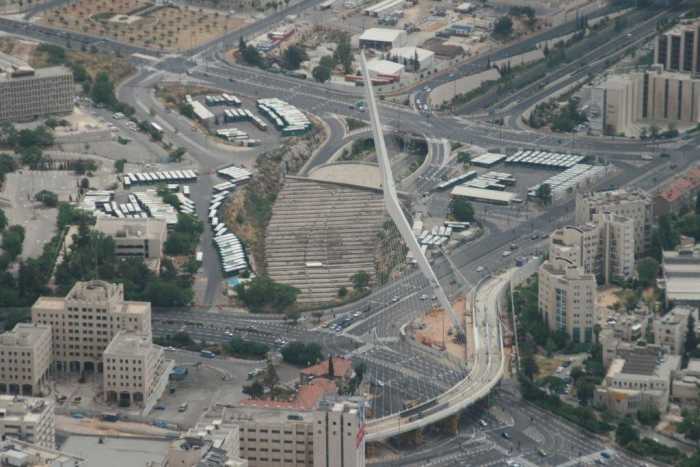
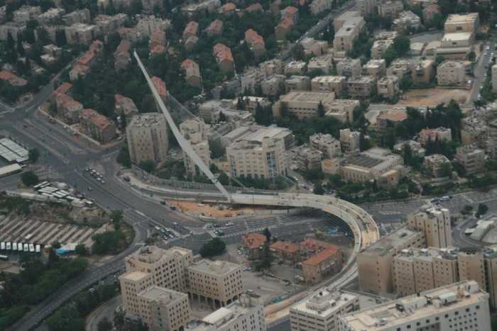
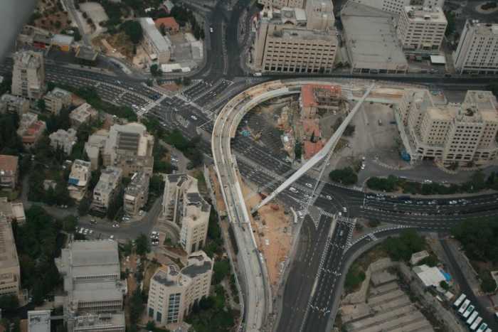
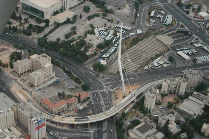
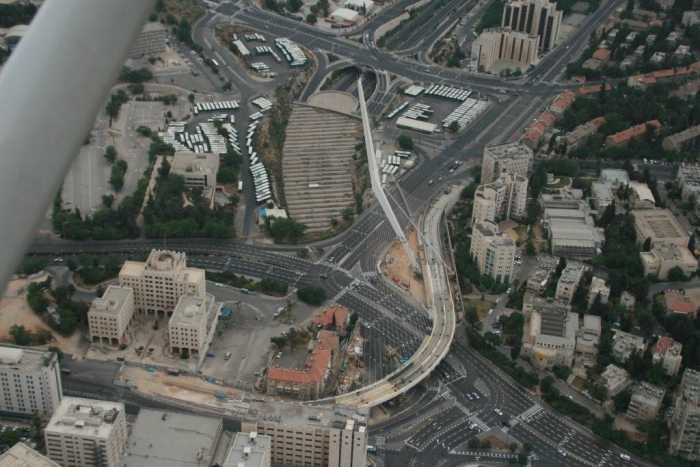
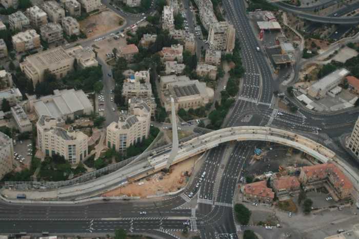
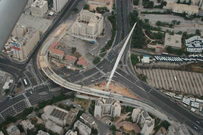
Jerusalem LRT Bridge (Jerusalem, Israel)
The structure is a cable-stay bridge constituted by
- a steel-box deck 160m long;
- a steel-box pylon 118m high;
- an anchor structure, called “parapet”, 74m long.
The steelworks are anchored to the ground by means of several holding down bolts of
diameter included between Ř45 and Ř140mm.
The total weight of the steelworks adds up to 4,200ton.
The pylon is connected to the deck and to the parapet by means of steel cables (Ř30, 40 and
50, with maximum length equal to 142m).
The pylon structure has an inclination of 30° in its own plane and of 15° towards the parapet
and it includes four stabilizing cables Ř90.
The strict architectural and urban requirements, the amazing shape of the elements with
imposed asymmetric geometries, the challenging weight-less appearance with reduced
sections but extremely high thicknesses make of this steel structure the most difficult and
delicate bridge ever conceived by Calatrava and, probably, by whoever architect or designer.
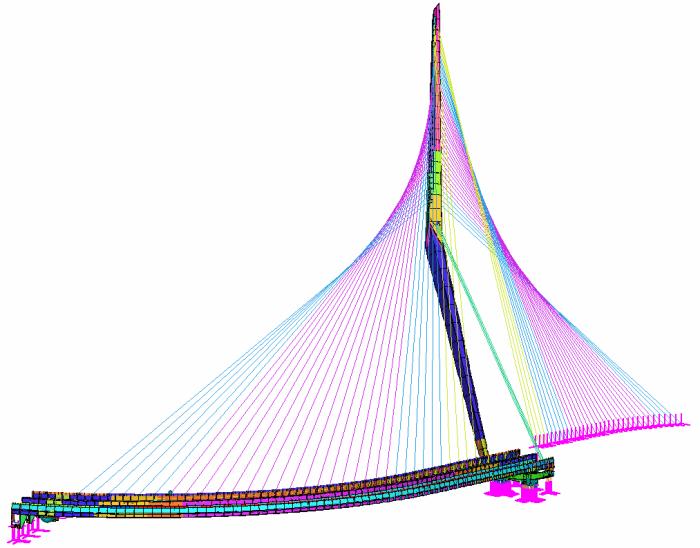
Straus7 FEM model and sub-models
Cimolai reviewed the structural design in strict cooperation with the studio Calatrava S.A.,
considering the erection and the exercise phases and simulating the structural behaviour with
a Finite Element Method model.
The definition of the model was as much challenging and complicated as the structure
unarguably is.
The following load combinations were considered and run:
• 137 SLU load combinations;
• 127 SLE load combinations.
Some parts of the structure, designed according to the architectural requirements, resulted in
being complicated and highly stressed. For an accurate investigation of the structural
suitability of these parts, some sub-models were generated in detailed brick elements.
|
The structure is a cable-stay bridge constituted by
- a steel-box deck 160m long;
- a steel-box pylon 118m high;
- an anchor structure, called “parapet”, 74m long.
The steelworks are anchored to the ground by means of several holding down bolts of
diameter included between Ř45 and Ř140mm.
The total weight of the steelworks adds up to 4,200ton.
The pylon is connected to the deck and to the parapet by means of steel cables (Ř30, 40 and
50, with maximum length equal to 142m).
The pylon structure has an inclination of 30° in its own plane and of 15° towards the parapet
and it includes four stabilizing cables Ř90.
The strict architectural and urban requirements, the amazing shape of the elements with
imposed asymmetric geometries, the challenging weight-less appearance with reduced
sections but extremely high thicknesses make of this steel structure the most difficult and
delicate bridge ever conceived by Calatrava and, probably, by whoever architect or designer.
|
|
Cimolai reviewed the structural design in strict cooperation with the studio Calatrava S.A.,
considering the erection and the exercise phases and simulating the structural behaviour with
a Finite Element Method model.
The definition of the model was as much challenging and complicated as the structure
unarguably is.
The following load combinations were considered and run:
• 137 SLU load combinations;
• 127 SLE load combinations.
Some parts of the structure, designed according to the architectural requirements, resulted in
being complicated and highly stressed. For an accurate investigation of the structural
suitability of these parts, some sub-models were generated in detailed brick elements.
|


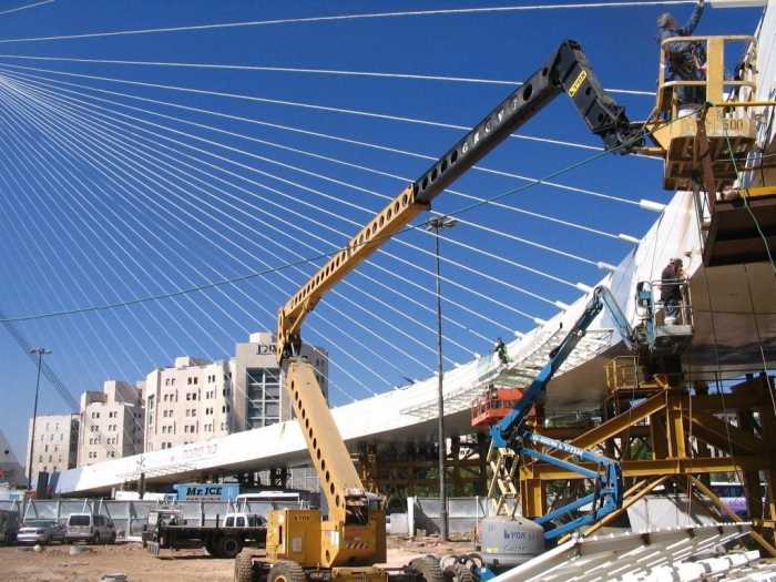
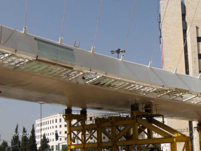
SOME PICTURES OF THE CONSTRUCTION SITE
Courtesy of CIMOLAI SPA
For further information about Straus7 please contact us by e-mail: straus7@hsh.info